
Teaching Tech 3D Printer Calibration
Useful? Considering supporting me:

This page serves as a companion for this video:
It aims to make calibrating your 3D printer as easy as possible. If you find it helps you and you would like to say thank you, here is a donation link: PayPal.me
Special thanks to my Patrons for suggesting this video and helping define the contents.
Watch the video and then work through each tab. I have created a custom gcode generator to assist in testing towers. Every attempt has been made to ensure this is safe but ultimately there always is risk in running presliced gcode from the internet. Preview the gcode in your slicer or Gcode.ws and print at your own risk.
To ensure there are no underlying problems with the frame or mechanical components.
Any time the frame or mechnical components have been disassembled or replaced.
It would be easy to use the techniques elsewhere on this page to try and fix problems that were actually caused by a problem with the physical components, so we will eliminate this first.
Many of these procedures are covered in this video: Complete beginner's guide to 3D printing - Assembly, tour, slicing, levelling and first prints
Move around the machine and check all fasteners. Crucial ones include those on the print head gantry such as those that hold the hot end on.
If your printer has a motion system based on V-roller wheels riding on V-slot extrusions, check they are properly tensioned. Each location will have one eccentric nut. This can be twisted to either add or remove tension on the wheels.
If the wheels are too loose: Wobble will be present in the assembly, which will show in the print as surface artefacts.
If the wheels are too tight: The assembly is will be too tense, which will wear the V-rollers prematurely.
Probably the most essential part of setting up your 3D printer. Most new users will trip up on this. My method is included in the above video and this diagram is a handy reference:

If your printer has PTFE tube, such as a bowden tube setup for the extruder/hot end, it is essential to make the tube is fully inserted and seated in the coupler. Also ensure the coupler is properly tightened. You may wish to use a small retaining clip on the coupler to prevent the tube working loose: Creality PTFE clip by morfidesign.
It is worth heating up te nozzle and pushing some filament through to see if it is exiting the nozzle properly. If the diameter is inconsistent or the extruded plastic shoots to one side, it may indicate a partial blockage in the nozzle that will be a pain in the future. It is also worth checking if the nozzle is properly tightened. Only do this when it is hot or you mau break it.
Ensure all belts are properly alinged and tensioned sufficiently.
Check all fans are spinning freely. This includes but is not limited to: mainboard cooling fan, heat sink fan, part cooling fan, PSU fan. It can be hard to diagose if a fan is performing at less than full capacity. It may be easier to simply replace than repair if you suspect a fan is failing.
To ensure the heating of the 3D printer nozzle and bed are safe, stable and consistent.
Any time the hot end is changed, including addng/removing a silicone sock or altering part cooling fan/ducts. Any time the bed is changed, such as adding a glass/mirror plate, magnetic spring steel sheet and/or under bed insulation.
This procedure is covered in this video: Two easy fixes for 3D printer temperature swings
In Marlin, this is a very straightforward process using M303.
Using a terminal such as Pronterface or Octoprint, enter the following for the hot end:
M303 E1 S200 U1
This will tune the hot end at 200 degrees. The S value can be altered to suit your most common printing temperature. The
M500
For the bed, PIDTEMPBED must be enabled in the firmware, then the command is quite similar:
M303 E-1 S60 U1
The bed is selected with E-1, and the temp set to 60 degrees. Substiture as necessary for your normal printing temperature. Once again save to EEPROM afterwards with:
M500
It may be preferable to have the printer as close to printing conditions as possible during these tuning prodecures. That means having filament loaded and the part cooling fan on for PLA temperatures.
To establish a baseline for comparison with later tests or before modifications.
Before general calibration or before a significant modification is to be fitted.
The form below will create a customised version of the XYZ 20mm calibration cube by iDig3Dprinting. It is fast to print and gives a good indication if there is any fundamental problem with the printer.
To determine the correct amount of steps Marlin firmware needs to send to the stepper motor for a desired movement.
Base calibration, as well as any time there has been a change to the extruder/hot end.
For the X, Y, and Z axes, the steper per mm is usually consistent between printers and rarely changes with modifications.
For the extruder however, variations in extruder hardware and filament means it is worth properly calibrating the extruder steps per mm, or E-steps.
This can be achieved using a terminal such as Pronterface or Octoprint by sending a series of gcode commands.
Firstly, we need to know the existing E-steps value. To find this, enter:
M92
M92 is used to report or set the steps per mm for each axis. M92 by itself will report the currents parameters. We want to make note of the number after E:

Now heat up your hot end to whatever temperature you usually print with. Once the temperature is stable, enter:
G91
G91 puts the printer in relative movement mode. Which means asking for 100mm adds 100mm to the current position, instead of moving to the exact position of 100mm.
Now we take a permanent marker and put a mark 120mm from the entry to the extruder.

G1 E100 F100
G91 sends a move command to the printer, in this case asking the extruder to advance 100mm at a speed of 100mm/sec.
The filament will then slowly go through the extruder and hot end. Once the extrusion finishes, we masure the distance between the mark and the entry to the extruder.
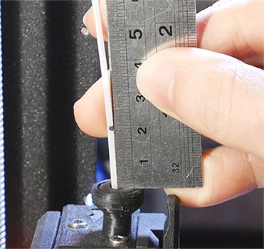
Ideally, 20mm remains, which means exactly 100mm was extruded. If your distance is anything other that this, complete the form below to calculate the correct E-steps:
To determine the correct amount filament to be extruded by the 3D printer as directed by the slicer.
Base calibration, as well as any time there has been a change to the extruder/hot end.
Our E-steps are now correct so we will move on to calibrating the slicer. Each slicer has setting to control the overall amount of filament extruded by the printer. If the flow rate is increased, more filament will be extruded. If the flow rate is descreased, less filament will be extruded.
In Simplify3D and PrusaSlicer, this is called Extrusion Multiplier. Cura calls it Flow.
My method of determining the correct flow rate is to print a single wall thick hollow cube, measure the actual thickness of the wall and then adjust the flow ratre to suit.
Unfortunately, I can't provide gcode for this process. It is vital to use gcode generated by YOUR slicer. The basic steps are covered in the video, and are repeated here.
| Step | Cura | Simplify3D | PrusaSlicer |
|---|---|---|---|
| 1. Import STL | cube STL | ||
| 2. Turn off infill | Infill > Infill density: 0% | General settings > Infill percentage: 0% | Print settings > Infill > Fill density: 0% |
| 3. Turn off top layers | Shell > Top thickness: 0 | Layer > Top solid layers: 0 | Print settings > Layers and perimeters > Horizontal layers > Top: 0 |
| 4. Ensure wall thickness is a known value Substitute whatver values you like here |
Shell > Wall thickness: 0.4 | Extruder > Extrusion width > manual > 0.4 | Print settings > Advanced > Extrusion width > Default extrusion width: 0.4 Print settings > Advanced > Extrusion width > Perimeters: 0.4 |
| 5. Set outer wall thickness to single extrusion | Shell > Wall line count: 1 | Layer > Outline/Perimeter shells: 1 | Print settings > Vertical shells > Perimeters: 1 |
| 6. Set flow rate to default 1.0 / 100% | Material > Flow: 100 | Extruder > Extrusion multiplier: 1.0 | Filament settings > Filament > Extrusion multiplier: 1 |
Now slice and print!
Use vernier calipers to measure the outer wall thickness of the hollow cube. Take measurements in multiple places/sides.
The following calculator can then be used to calculate the new flow rate:
| Cura | Simplify3D / PrusaSlicer |
|---|---|
What you see with your eyes is more important tha a theoretical calculation. After you have performed this calibration, please adjust the flow rate higher or lower based on what you actually see.
For example, take the cube shown in the thumbnail of the XYZ 20mm calibration cube by iDig3Dprinting:

This print shows clear signs of under extrusion. Despite what any calibration procedure determined, the flow rate for this slicer/printer combination needs to be increased.